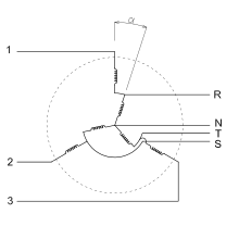

An induction regulator is an alternating current electrical machine, somewhat similar to an induction motor, which can provide a continuously variable output voltage. The induction regulator was an early device used to control the voltage of electric networks. Since the 1930s it has been replaced in distribution network applications by the tap transformer. Its usage is now mostly confined to electrical laboratories, electrochemical processes and arc welding. With minor variations, its setup can be used as a phase-shifting power transformer.
© MMXXIII Rich X Search. We shall prevail. All rights reserved. Rich X Search
