Back أنبوب مغناطيسي إلكتروني Arabic Magnetrón AST Магнетрон Bulgarian ম্যাগনিট্রন Bengali/Bangla Magnetró Catalan Magnetron Czech Magnetron Danish Magnetron German Magnetrón Spanish Magnetron Estonian


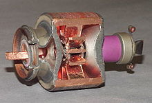
The cavity magnetron is a high-power vacuum tube used in early radar systems and subsequently in microwave ovens and in linear particle accelerators. A cavity magnetron generates microwaves using the interaction of a stream of electrons with a magnetic field, while moving past a series of cavity resonators, which are small, open cavities in a metal block. Electrons pass by the cavities and cause microwaves to oscillate within, similar to the functioning of a whistle producing a tone when excited by an air stream blown past its opening. The resonant frequency of the arrangement is determined by the cavities' physical dimensions. Unlike other vacuum tubes, such as a klystron or a traveling-wave tube (TWT), the magnetron cannot function as an amplifier for increasing the intensity of an applied microwave signal; the magnetron serves solely as an electronic oscillator generating a microwave signal from direct current electricity supplied to the vacuum tube.
The use of magnetic fields as a means to control the flow of an electric current was spurred by the invention of the Audion by Lee de Forest in 1906. Albert Hull of General Electric Research Laboratory, USA, began development of magnetrons to avoid de Forest's patents,[1] but these were never completely successful. Other experimenters picked up on Hull's work and a key advance, the use of two cathodes, was introduced by Habann in Germany in 1924. Further research was limited until Okabe's 1929 Japanese paper noting the production of centimeter-wavelength signals, which led to worldwide interest. The development of magnetrons with multiple cathodes was proposed by A. L. Samuel of Bell Telephone Laboratories in 1934, leading to designs by Postumus in 1934 and Hans Hollmann in 1935. Production was taken up by Philips, General Electric Company (GEC), Telefunken and others, limited to perhaps 10 W output. By this time the klystron was producing more power and the magnetron was not widely used, although a 300W device was built by Aleksereff and Malearoff in the USSR in 1936 (published in 1940).[1]
The cavity magnetron was a radical improvement introduced by John Randall and Harry Boot at the University of Birmingham, England in 1940.[2]: 24–26 [3] Their first working example produced hundreds of watts at 10 cm wavelength, an unprecedented achievement.[4][5] Within weeks, engineers at GEC had improved this to well over a kilowatt, and within months 25 kilowatts, over 100 kW by 1941 and pushing towards a megawatt by 1943. The high power pulses were generated from a device the size of a small book and transmitted from an antenna only centimeters long, reducing the size of practical radar systems by orders of magnitude.[6] New radars appeared for night-fighters, anti-submarine aircraft and even the smallest escort ships,[6] and from that point on the Allies of World War II held a lead in radar that their counterparts in Germany and Japan were never able to close. By the end of the war, practically every Allied radar was based on the magnetron.
The magnetron continued to be used in radar in the post-war period but fell from favour in the 1960s as high-power klystrons and traveling-wave tubes emerged. A key characteristic of the magnetron is that its output signal changes from pulse to pulse, both in frequency and phase. This renders it less suitable for pulse-to-pulse comparisons for performing moving target indication and removing "clutter" from the radar display.[7] The magnetron remains in use in some radar systems, but has become much more common as a low-cost source for microwave ovens. In this form, over one billion magnetrons are in use today.[7][8]
- ^ a b Redhead, Paul A., "The Invention of the Cavity Magnetron and its Introduction into Canada and the U.S.A.", La Physique au Canada, November 2001
- ^ Fine, Norman (2019). Blind Bombing: How Microwave Radar brought the Allies to D-Day and Victory in World War II. Nebraska: Potomac Books/University of Nebraska Press. pp. 24–26. ISBN 978-1640-12279-6.
- ^ "The Magnetron". Bournemouth University. 1995–2009. Archived from the original on 26 July 2011. Retrieved 23 August 2009.
- ^ Fine 2019, pp. 24–26.
- ^ Cite error: The named reference
Magnetronwas invoked but never defined (see the help page). - ^ a b Schroter, B. (Spring 2008). "How important was Tizard's Box of Tricks?" (PDF). Imperial Engineer. 8: 10. Archived (PDF) from the original on 2011-06-17. Retrieved 2009-08-23.
- ^ a b Brookner, Eli (19–20 April 2010). "From $10,000 magee to $7 magee and $10 transmitter and receiver (T/R) on single chip". 2010 International Conference on the Origins and Evolution of the Cavity Magnetron. pp. 1–2. doi:10.1109/CAVMAG.2010.5565574. ISBN 978-1-4244-5609-3.
- ^ Ma, L. "3D Computer Modeling of Magnetrons Archived 2008-10-10 at the Wayback Machine." University of London Ph.D. Thesis. December 2004. Accessed 2009-08-23.
© MMXXIII Rich X Search. We shall prevail. All rights reserved. Rich X Search